
Replacing the STP protocol allows the network to support a fabric topology (tree, ring, mesh, or core/edge) while avoiding ISL bottlenecks, since more ISLs become active as traffic volume grows.

Flatter networks also include elimination of STP and LAG.

In addition, it helps prevent resources in a data center from becoming stranded and not efficiently usable. It also relieves the operations staff from having to worry about the “affinity” of application components in order to provide good performance.

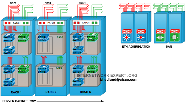
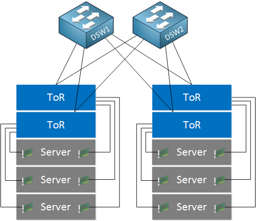
This flat connectivity simplifies the writing of applications since there is no need to worry about the performance hierarchy of communication paths inside the data center. A flat network also implies creating larger Layer 2 domains (connectivity between such domains will still require some Layer 3 functionality). Most networking engineers agree that a flat fabric also implies that connected devices can communicate with each other without using an intermediate router. Topologically, a “flat” network architecture implies removing tiers from a traditional hierarchical data center network such that it collapses into a two-tier network (access switches, also known as top of rack (TOR) switches, and core switches). This would significantly reduce both operating and capital expense. Many clients are seeking a flattened network that clusters a set of switches into one large (virtual) switch fabric. However, LAGs have their own limitations, for example, they must be manually configured on each switch port. To overcome this, link aggregation groups (LAGs) were standardized, so that multiple links between switches could be treated as a single logical connection without forming loops. This means that ISL bandwidth is limited to a single logical connection, since multiple connections are prohibited. Network loops are prevented by using STP, which allows only one active path between any two switches. This adds latency and potentially creates congestion on interswitch links (ISLs). In order for data to flow between racks of servers and storage, data traffic needs to travel up and down a logical tree structure as shown in Figure 1.1. The movement of traffic between switches is commonly referred to as “hops” in the network (there are actually more precise technical definitions of what constitutes a “hop” in different types of networks, which will be discussed in more detail later). Each tier has specific design considerations and data movement between these layers is known as multitiering. Casimer DeCusatis, in Handbook of Fiber Optic Data Communication (Fourth Edition), 2013 1.1.1 Flattened, converged networksĬlassic Ethernet networks are hierarchical, as shown in Figure 1.1, with three, four, or more tiers (such as the access, aggregation, and core switch layers).


 0 kommentar(er)
